Hood design BIW (Body-In-White)
Contents
- 1. Abstract
- 2. Introduction
- 3. Given Data
- 4. Material and Manufacturing Process
- 4.1. Material
- 4.2. Manufacturing Process
- 5. Design
- 5.1. Draft Analysis
- 5.2. Flexural Rigidity
- 5.3. Pedestrian safety regulations
- 5.4. Hinge and Striker placement angle
- 5.5. Reinforcements
- 5.6. Vehicle crash safety features
- 5.7. Assembly
- 5.7.1. Mastic sealant
- 5.7.2. Hemming
- 5.7.3. Spot Welding
- 5.7.4. Stopper Mounting features
- 6. Conclusion
- 7. Bibliography
1. Abstract
This paper studies the design and development of the hood of a car while focusing on all the features involved in its design. A brief literature review on the material and the manufacturing process used to develop the hood is done at the start before diving deep into the comprehension of all the features used to design the hood and the design intent behind them.
2. Introduction
Body-in-white (BIW) is the name given to a car body’s sheet when all its components—barring moving parts (e.g., hoods, fenders, etc.), trims (e.g., glass, seats, etc.), or chassis subassemblies—have been welded together. (Pradeep et al. 2017)

Figure 2.1 Body-in-White (BIW) Structure (Mallick 2021)
The body-in-white (BIW) splits down into the main structure, ‘body-less-doors’, and the ‘bolt-on’ or skin assemblies. Each of these in turn break down into the inner panel, usually deep drawn to provide bulk shape and rigidity, plus the shallow skin panels, which provide the outer contour of the body shape and require more aesthetic properties such as smooth blemish-free surface and scuff or dent resistance. The key elements of the main structure are the floor and main cage containing ‘A’, ‘B/C’ and ‘D’ posts or corner pillars and roof/cantrail surround, plus closed sections such as cross members, and front and rear longitudinal sections, which provide essential impact resistance. The requirements of each zone are summarized in Table 1.1, together with recommendations for appropriate steels and possible alternatives. Figure 1.3 shows the state-of-the-art deployment of steels within the body structure of a typical family sedan. (Davies 2012a)

Figure 2.2 Body-in-White Panels Exploded view (Mallick 2021)
Table 2.1 Requirements of Different Panels Comprising the BIW Structure (Davies 2012a)
| Zone/Assembly | Requirements | Type | YS (MPa) | Possible Alternatives (Material/Form)∗ |
|---|---|---|---|---|
| Main Structure | ||||
| Front/rear longitudinal members | Impact resistance | HSS | 300 | DP600, AP |
| A-post inner/outer | Rigidity, strength | HSS | 300 | AP, HT |
| Cantrail | Rigidity, strength | HSS | 260 | AP, HT |
| Main/rear floor | Moderate strength | HSS | 180 | AS |
| Bodyside | Moderate strength, formability | HSS | 180 | AS, TWB |
| Spare wheel well | Deep drawability | FS | 140 | SWS, SPA |
| Wheelhouse, valance | Formability | FS | 140 | AS |
| ‘Bolt-on’ Assemblies | ||||
| Outer Panels | ||||
| Door skins | A’ class surface, dent resistance | FS | 140 | BH180, AS, SPA PLA-RRIM |
| Hood | ‘A’ class surface, dent resistance | FS | 140 | BH180, AS, SPA PLA-SMC |
| Trunk | ‘A’ class surface, dent resistance | FS | 140 | BH180, AS, SPA PLA-SMC |
| Roof | ‘A’ class surface, dent resistance | FS | 140 | BH180, HS |
| Inner Panels | ||||
| Doors | Drawability | FS | 140 | TWB |
| Intrusion beams, rails | High-impact strength | UHS | 1200 | AT, DP600+ |
*AP, aluminum profile; AS, aluminum sheet; BH180, bake-hardened steel; DP, dual phase steel; FS, forming steel; HS, hydroformed sheet; HSS, high-strength steel; HT, hydroformed tube; PLA-xxx, plastic-xxx type; RRIM, reinforced reaction injection molding; SMC, sheet molding compound; SPA, superplastic Al; SWS, sandwich steel; TWB, tailor-welded blank; UHS, ultra HS steel

Figure 2.3 Utilization of higher strength steels and tailor welded blanks (Davies 2012a)

Figure 2.4 Contribution of body-in-white to overall vehicle weight (Davies 2012b)

Figure 2.5 Sheet steel content/form within the overall vehicle construction of a typical family car (Davies 2012b)
3. Given Data
The following data was provided to design the hood inner panel and show hemming on the hood outer panel:
- Hood Outer Panel/Skin Data (Figure 2.1)
- Hinge CAD data (Figure 2.2)
- Striker CAD data (Figure 2.3)
- Master Sketch (Figure 2.4)
- Hemming Data (Figure 2.5)
- Rear Section Relief dimensions (Figure 2.6)
- Front Section Relief dimensions (Figure 2.7)
- Hood Thickness Information:
- Outer Panel Thickness = 0.75mm
- Inner Panel Thickness = 0.75mm
- Reinforcement Thickness = 1.5mm

Figure 3.1 Hood Outer Panel/Skin data

Figure 3.2 Hinge CAD Data

Figure 3.3 Striker CAD Data

Figure 3.4 Master Sketch

Figure 3.5 Hemming Data

Figure 3.6 Rear Section Relief Dimensions

Figure 3.7 Front Section Relief Dimensions
4. Material and Manufacturing Process
Understanding what the material is and the manufacturing process used to manufacture the component being designed is very important before designing any component. Design for manufacturing helps achieve a superior product at a lower cost and is highly desirable.
4.1. Material
BiW is expected to possess a number of significant properties. It must have high tensile strength as well as high stiffness—bending, torsional, static, and dynamic. It must also provide good quality safety both to the car body and to its occupants against crashes of all kinds—front, rear, side, or even rollover, meeting the Federal Motor Vehicle Safety Standard No. 208. It should also be able to protect occupants from noise, vibration, and/or harshness (NVH) by absorbing or reducing these conditions. Also, it should be easy to weld and form, as well as be highly paintable and easy to design. It should provide a good surface finish that is smooth, and should also be corrosion resistant. Improvement of fuel economy also necessitates the use of lightweight materials in BiW, as it constitutes a significant share of car’s weight; in addition, given environmental concerns in recent times, it is also expected to be recyclable. Given such extensive requirements, only steel and aluminum have been used for making BiW; the former is preferred for its high strength and low cost, while the latter is preferred for its lower density that helps reduce car weight (Roth, Clark, and Kelkar 2001), (Ahrens et al. 2009). Table 3.1 details the materials generally used for making BiW, along with their properties. (Pradeep et al. 2017)
Table 4.1 Properties of BiW Materials (Pradeep et al. 2017)
| Material | Yield Strength (MPa) | Ultimate Tensile Strength (MPa) | Reference |
|---|---|---|---|
| Steel | 210–1250 | 340–1520 | (Mohanty 2004) |
| Aluminum | 90 | 195 | (Reichenbach 2021) |
| CFRP | 250-585 | (Ahmed 2018) |
Table 4.2 Design and material requirements for body structure and body panel in a BIW construction (Mallick 2021)
| Body structure | Body panel |
|---|---|
| Bending stiffness | Bending stiffness |
| Torsional stiffness | Oil canning (outer panel) |
| First bending frequency | Dent resistance (outer panel) |
| First torsional frequency | First bending frequency |
| Crashworthiness | Surface finish (Class A) and smoothness (outer panel) |
| Fatigue | Painting characteristics (outer panel) |
| Corrosion resistance | Corrosion resistance |
| Formability | Formability |
| Joining | Attachment |
| Recycling | Recycling |
BIW, Body-in-white.
Table 4.3 Key Design Parameters and Relevant Processing Details (Davies 2012c)
| Parameter | Relevance | Influencing Factors and Key Processing Stages |
|---|---|---|
| Strength | Design | Imparted by composition, deformation and grain size; alloying during smelting and mechanical and thermal treatment |
| Ductility | Forming, collapse characteristics | Lean composition and optimum heat treatment; careful analysis and extended annealing cycle |
| Drawability index ‘r’ (resistance to thinning)∗ | Press forming | Crystallographic texture requiring optimum rolling and annealing schedules |
| Work hardenability ‘n’∗ | Stretch forming, energy absorption | Composition and grain size dependent; casting and rolling |
| Surface finish | Lubricity during forming, painted appearance | Imparted by roll finish at temper rolling stage |
Table 4.4 Main Criteria and Ratings for Realistic Selection of Automotive Body Materials (Davies 2012c)
| Material | Design Parameters | Ease of Manufacturing (‘Process Chain’)∗ | Environmental ‘Friendliness’∗ | Cost | |||||||
|---|---|---|---|---|---|---|---|---|---|---|---|
| Criteria | YS (MPa) | UTS (MPa) | A80 (min%) | E. Mod (GPa) | D (g/cm3) | Forming | Joining | Paint | CO2 + Emissions | Disposal (ELV) | Forming Steel = 1 |
| Forming grade steel EN 10130 DCO4 + Z | 140 min | 270 min | 40 | 210 | 7.87 | 8 | 9 | 9 | 7 | 9 | 1.0 |
| HSS EN 10292 H300YD + Z | 300 min | 400 min | 26 | 210 | 7.87 | 6 | 8 | 9 | 8 | 8.5 | 1.1 |
| UHSS – martensitic | 1050–1250 | 1350–1550 | 5 | 210 | 7.87 | 4 | 7 | 9 | 8 | 8.5 | 1.5 |
| Aluminum 5xxx | 110 min | 240 min | 23 | 69 | 2.69 | 6 | 5 | 8 | 9 | 9 | 4.0 |
| Aluminum 6xxx | 120 min | 250 min | 24 | 69 | 2.69 | 6 | 5 | 8 | 9 | 9 | 5.0 |
| Magnesium sheet | 160 min | 240 min | 7 | 45 | 1.75 | 4 | 4 | 7 | 9.5 | 6 | 4.0 |
| Titanium sheet | 880 min | 924 min | 5 | 110 | 4.50 | 6 | 5 | 7 | 9 | 6 | 60.0 |
| GRP | 950 | 400–1800 | <2.0 | 40 | 1.95 | 8 | 7 | 8 | 8 | 5 | 8.0 |
| Carbon fiber composite | 1100 | 1200–2250 | <2.0 | 120-250 | 1.60-1.90 | 8 | 7 | 8 | 9 | 5 | 50.0+ |
*Based on range: 1 = difficult to process; 10 = production without difficulty
**Ease with which prevailing legislation can be met: 1 = extensive development required; 10 = without difficulty
Steel is still the predominant material used for manufacture (Dieffenbach 1999), (Davies and Easterlow 1985) and the generally high ratings levels shown under the ‘ease of manufacture’ column reflect the provision already made by the industry for compatible facilities. The lower ratings for the processing of aluminum do not necessarily indicate that these newer materials are inferior; rather, they are indicative of the need to introduce new practices and of the size of change needed to accommodate them. Table 3.3 indicates the ‘pain’ necessary to implement these lighter, but sometimes problematic, alternative materials. Figures are also included for polymeric materials, frequently used in specialist car manufacture, and carbon fiber composites used in competition vehicles. (Davies 2012c)
Steel has demonstrated all-round versatility over many years and its cost has remained reasonable. The life of pressed components has been extended through the use of zinc-coating technology, and the range of strength levels has increased to meet increasingly stringent engineering needs. Importantly, it is very adaptable with regard to corrective rework, an advantage that is often overlooked. This may be required on-line, to rectify production defects, which can sometimes occur even with the best of manufacturing systems, or for repair purposes following accidental damage in service. However, experience has shown that steel is highly tolerant to reshaping and a large infrastructure of skills and materials exist to restore the structure to meet the original engineering specification. The importance of ease and cost of repair has become increasingly apparent with the emergence of newer grades of high-strength steel, aluminum and other materials. These newer materials require precise retreatments and involve more sophisticated equipment to ensure that original standards are achieved. This can also have a bearing on the insurance category derived for specific vehicles. (Davies 2012b)
Put simply, the advantages of steel as an autobody material include its :
- low cost
- ease of forming
- consistency of supply
- corrosion resistance with zinc coatings
- ease of joining
- recyclability
- good crash energy absorption
The main disadvantages of steel in autobody applications are:
- it is heavier than alternative materials
- it can corrode if uncoated
However, both these factors have been addressed over the last 20 years through the development of a much wider range of sheet and strip products. (Davies 2012c)
4.2. Manufacturing Process
The Primary Process involved in manufacturing BiW components is Deep Drawing/Stamping. This process is usually followed by other processes like blanking, piercing, trimming, etc.
Deep drawing is one of the most commonly used metal forming techniques. It is used by numerous sectors, including the automotive, medical, manufacturing, and aerospace industries, to create various parts and complex shapes from metal sheets.
The deep drawing process begins by placing a flat piece of sheet metal on a forming die. The workpiece is then held in place via a compressive force exerted by a blank holder, which controls the sliding of the metal sheet during the drawing process. The punching tool then moves down to the workpiece, causing it to deform. The metal flows into the die cavity to create the final shape, which is typically hollow and open on one side. The term “deep drawing” refers to the shapes produced by this method, as they often have depths that exceed their diameter. (Anon n.d.)

Figure 4.1 Deep drawn Side Body panel
The deep drawing process is widely used in the industry because it eliminates costly operations such as welding and machining and fabricates parts with reduced weight and good mechanical properties in few operations and at high production rates (Medellín-Castillo et al. 2013).
The automotive industry maintains a constant demand for components that are high-strength and leak resistant. Deep drawn automotive components benefit from strain hardening during the molding process, and as such, are ideal for automotive uses. Strain hardening increases the strength properties of the metal, which makes it more durable in harsh automotive applications. Also, since deep drawn parts are created from a single sheet of metal, the final component contains no seams, which can be susceptible to leaks (Anon n.d.).
5. Design
Using the given data, the inner panel was designed in CATIA V5 R21 by offsetting the original outer panel and introducing the required features as per the design intent.
5.1. Draft Analysis

Figure 5.1 Complete Assembly
Since it was already understood that the material was steel and the manufacturing process is deep drawing, a draft angle of at least 7 degrees was maintained to facilitate the deep drawing manufacturing process as can be seen from the draft analysis in Figure 4.2.
The features used and the fillets given throughout the design were in consideration of facilitating the deep drawing manufacturing process. Effort was put in to make sure the material flow was as laminar as possible to minimize the development of stresses and avoid other drawing errors like buckling, wrinkling, earing, etc.

Figure 5.2 Draft Analysis of Inner Panel
5.2. Flexural Rigidity
Flexural Rigidity is the mechanical property that tells us how stiff a structure is. It is the resistance offered by a structure while undergoing bending. Mathematically it is defined as:
Flexural Rigidity = EI
Where,
E = Flexural Modulus (The ratio of stress to strain in flexural deformation)
I = Area Moment of Inertia

Figure 5.3 Flexural Rigidity definition
The main purpose of an inner panel is to increase stiffness and strength of the outer panel without a significant increase in weight of the overall hood. The bending stiffness is a very important criteria to be achieved and the design of the inner panel has to emulate this design intent. Higher stiffness is also necessary for NVH (Noise, Vibration and Harshness) considerations (Mallick 2021).
As can be seen from the mathematical expression for Flexural Rigidity, we know that it is directly dependent on two factors which are material and area moment of inertia.

Figure 5.4 Area Moment of Inertia definition
Area moment of inertia gives us an insight into how the area is distributed about the reference axis. The farther the distributed area from the reference axis, the more the area moment of inertia for that cross-section. The more the area moment of inertia, the higher the flexural rigidity and hence higher the overall stiffness of the hood. Therefore, the design of the hood inner panel was done such that the overall hood assembly’s (i.e. both the outer panel and the inner panel) area moment of inertia increases while conforming to the constraints of outer panel curvature, mastic sealant placement restrictions, Pedestrian safety considerations, crash safety considerations and ease of manufacturability considerations.
Area moment of inertia is a major factor which has more freedom of change because of the constraint of material choice and panel thickness which otherwise could’ve been used to increase the elastic modulus and thickness to achieve a higher stiffness. Thus, a clever use of design is made in how and where the curvature flows and embosses are given to achieve a higher ‘area moment of inertia’ without considerably increasing the weight of the hood as a whole and reaching the desired target parameters like stiffness, strength and weight.
In Figure 4.5 a plain design of inner panel with no embosses shows the area moment of inertia to be lower than the one shown in Figure 4.6 which is the actual design with multiple embosses. Comparing the values from these figures in
Area moment of inertia is a measure of how Higher Stiffness is achieved by improving the geometry such that the ‘area moment of inertia’ is increased, since Area moment of inertia is inversely proportional to deflection and directly proportional to stiffness.
Table 5.1 Moment of Inertia comparison
| Section Modulus with zero embosses | Section Modulus of actual design | Difference | |
|---|---|---|---|
| IoxG | 187392.127 mm4 | 263815.312 mm4 | 76423.185mm4 |
| IoyG | 8.905e+007 mm4 | 9.164e+007 mm4 | 2.590e+006 mm4 |

Figure 5.5 Section Modulus of Design with zero embosses

Figure 5.6 Section Modulus of the actual design
5.3. Pedestrian safety regulations
The hood is a very important closure component in a car because of its location. It is a key frontal impact member along with the bumper in the event of a crash or collision with other vehicles, trees, etc. and mainly pedestrians. Although the NHTSA (National Highway Traffic Safety Administration) is not as strict with pedestrian safety requirements, the Euro NCAP regulations and the JNCAP regulations are meticulous (Office 2020), (van Ratingen and Williams 2014).

Figure 5.7 Example of Euro NCAP requirements pedestrian head impact safety requirements (van Ratingen and Williams 2014)

Figure 5.8 Wrap Around distance as per Euro NCAP regulations (van Ratingen and Williams 2014)

Figure 5.9 Headform test area (van Ratingen and Williams 2014)

Figure 5.10 Labelling of headform grip points (van Ratingen and Williams 2014)
Figure 4.7, Figure 4.8, Figure 4.9 & Figure 4.10 show an insight into some of the requirements for pedestrian safety when designing the hood. The hood needs to meet minimum strength requirements but it should also have crumple zones at strategic locations of pedestrian head impact to protect the pedestrian from serious injury. To accommodate this crumple zone requirement, cutouts are introduced strategically as shown in Figure 4.11 in the hood inner panel.

Figure 5.11 Cutouts in the hood inner panel for pedestrian safety
5.4. Hinge and Striker placement angle
The hinge and striker should be placed on a surface such that when the hood is closed the striker should very precisely place onto the latch in the engine compartment to lock the hood in place. Therefore, the hinge axis should pass through the center of an imaginary circle where the maxima of the striker should always be coincident with the trajectory of the circle as shown in Figure 4.13.

Figure 5.12 Inner Panel with Hinges and Striker

Figure 5.13 Hinge and Striker placement reference circle trajectory
5.5 Reinforcements
At the hinge area there is continuous flexing of material and at the striker area there is continuous impact. The mounting of the hinge and the striker components on a thin 0.75mm inner panel when the forces and bending moments previously mentioned will be applied multiple times over the lifetime of the vehicle, crack generation, deformation, tearing, etc. can take place. To reduce this phenomenon and increase the lifetime of the hood, we introduce reinforcements of thickness 1.5mm in these areas as shown in Figure 4.14.

Figure 5.14 Reinforcements
The reinforcements were designed considering sheet metal trimming, bending and punching to be the main manufacturing operations performed to arrive at the final reinforcement. If the corners were also to be considered then manufacturing would involve deep drawing which would significantly increase cost which is assumed to be unnecessary because of the high tooling cost. Relief is given in the edges to simplify GD&T requirements, which reduces their overall manufacturing cost due to a more accommodating GD&T.

Figure 5.15 Striker component reinforcement

Figure 5.16 Hinge(L) Reinforcement
5.6 Vehicle crash safety features
The grooves seen on the hood inner panel are in a Y formation or directed towards the edges of the hood towards the hinges as shown in Figure 4.17. This is done to distribute the impact forces during a frontal impact collision towards the side body members of the car instead of dissipating them into the car cabin and to the passenger

Figure 5.17 Grooves in Y formation for energy dissipation to side members in a frontal impact collision
The lateral groove as shown in Figure 4.18 in the center of the hood is to provide a weak point and a crumple zone for the hood to collapse in the event of a frontal impact collision to dissipate the force and also increase the time it takes for the force to travel to the passenger. These are called crash initiators.

Figure 5.18 Lateral Groove Crumple Zone

Figure 5.19 Crashed Car Hood (Anon n.d.)
This direction of force dissipation and the increase in time due to the above features assists the seatbelt and the airbag deployment system by providing enough time to deploy and reduce the whiplash effect as shown in Figure 4.20.

Figure 5.20 Whiplash effect (Anon n.d.)
5.7. Assembly
The components to be assembled are:
- Inner Panel
- Outer Panel
- Hinge(L) Reinforcement
- Hinge(R) Reinforcement
- Striker Reinforcement
- Hinge(L)
- Hinge(R)
- Striker
5.7.1 Mastic sealant
The hood inner panel and outer panel are joined using the mastic sealant instead of welding or other joining methods because the outer panel is a cosmetic part and it needs to have a smooth and attractive surface finish. The mastic sealant also further improves the flexural rigidity of the entire assembly. The mastic points where the mastic sealant is placed were strategically chosen because the mastic sealant is generally known to have approximately 80mm circular area of influence as shown in Figure 4.21.

Figure 5.21 Mastic Points area of influence
The gap between the outer panel and the inner panel should be less than 5mm for the mastic sealants to be effective and therefore, a gap of approx. 2.48mm was maintained at the mastic point areas between the outer panel and the inner panel as shown in Figure 4.22.

Figure 5.22 Gap between inner panel and outer panel for mastic sealant
5.7.2 Hemming
The outer panel is a cosmetic part and again spots from spot welding or unevenness caused due to welding or any other joining method that would jeopardize the appearance of the hood cannot be used. Hence, hemming is used to join the outer panel and the inner panel as shown in Figure 4.23

Figure 5.23 Hemmed outer panel

Figure 5.24 Roller Hemming process
As per hemming requirements, appropriate reliefs were given at necessary curvatures to further assist the hemming process as shown in Figure 4.25 and Figure 4.26.

Figure 5.25 Rear Right Hemming Relief

Figure 5.26 Front Right Hemming Relief
5.7.3. Spot Welding
The inner panel is not a cosmetic part as much as the outer panel and thus spot welding is acceptable and is used to weld the hinge and the striker reinforcements onto the inner panel as shown in Figure 4.27

Figure 5.27 Spot welding
5.7.4. Stopper Mounting features
The hood sits on the engine compartment using stoppers and features for stopper mounting have also been provided on the inner panel as shown in Figure 4.28. The stoppers also protect the hood as well as the engine compartment from impact when it is being closed and they can be easily replaced instead of the entire hood in case of NVH issues due to wear and tear.

Figure 5.28 Stopper mounting features
The stoppers also protect the hood as well as the engine compartment from impact when it is being closed and they can be easily replaced instead of the entire hood in case of NVH issues due to wear and tear.
6. Conclusion
The hood was designed and developed following general guidelines and with a spark of creativity wherever possible. Meticulous care has been taken in understanding the design intent in developing a BIW hood while designing every feature. Changes in design can be made based on CAE analysis from the CAE team. Further features, different cutout geometry, mastic placement, etc. can be done based on engine compartment information. Gas stay features can be included if gas stay information is provided. Other features for trim placement and mounting and also for robot grip during manufacturing and electrodeposition processes can be provided if data is available.
7. Bibliography
Ahmed, Shamil K. 2018. “Ultimate Strength and Axial Strain of FRP Strengthened Circular Concrete Columns.” Cogent Engineering 5(1):1501971.
Ahrens, Gritt, Torsten Dellmann, Stefan Gies, Markus Hecht, Hamid Hefazi, Rolf Henke, Stefan Pischinger, Roger Schaufele, and Oliver Tegel. 2009. “Transport Systems.” in Springer Handbook of Mechanical Engineering.
Anon. n.d. “A23f6209107c740ed87ab4e00c42fac22f13cb4c @ Www.Thomasnet.Com.”
Anon. n.d. “Ada7236539d26e238f7e6574b0d4bf5517b1e5d5 @ Www.Toddsautobody.Net.”
Anon. n.d. “Ec05512e39c3720753da474f77c952d44e98f5e3 @ Www.Nelsonmacneil.Com.”
Davies, G., and R. A. Easterlow. 1985. “Automotive Design and Material Selections.” Metals and Materials (London) 1(1):20–25.
Davies, Geoffrey. 2012a. “Design and Material Utilization.” Materials for Automobile Bodies 17–91. doi: 10.1016/B978-0-08-096979-4.00002-5.
Davies, Geoffrey. 2012b. “Introduction.” Materials for Automobile Bodies 1–16. doi: 10.1016/B978-0-08-096979-4.00001-3.
Davies, Geoffrey. 2012c. “Materials for Consideration and Use in Automotive Body Structures.” Materials for Automobile Bodies 93–143. doi: 10.1016/B978-0-08-096979-4.00003-7.
Dieffenbach, Jeff R. 1999. Not the Delorean Revisited: An Assessment of the Competitive Position of a Stainless Steel Body-in-White. SAE Technical Paper.
Mallick, P. K. 2021. “Designing Lightweight Vehicle Body.” Materials, Design and Manufacturing for Lightweight Vehicles 405–32. doi: 10.1016/B978-0-12-818712-8.00010-0.
Medellín-Castillo, Hugo I., Pedro De J. García-Zugasti, Dirk F. De Lange, and Francisco J. Colorado-Alonso. 2013. “Analysis of the Allowable Deep Drawing Height of Rectangular Steel Parts.” International Journal of Advanced Manufacturing Technology 66(1–4):371–80. doi: 10.1007/s00170-012-4331-9.
Mohanty, O. N. 2004. “Steels for the New Millennium Auto: Challenges and Opportunities: In ‘Futuristic Materials.’” Pp. 83–99 in Proc. of national seminar, Bhubaneswar.
Office, U. S. Government Accountability. 2020. “Pedestrian Safety: NHTSA Needs to Decide Whether to Include Pedestrian Safety Tests in Its New Car Assessment Program.” (April):70p.
Pradeep, Sai Aditya, Rakesh K. Iyer, Hakan Kazan, and Srikanth Pilla. 2017. “Automotive Applications of Plastics: Past, Present, and Future.” Applied Plastics Engineering Handbook: Processing, Materials, and Applications: Second Edition 651–73. doi: 10.1016/B978-0-323-39040-8.00031-6.
van Ratingen, M., and A. Williams. 2014. “The European New Car Assessment Programme.” Journal of the Australasian College of Road Safety 25(2):52–55.
Reichenbach, Michael. 2021. “We Can Reduce Carbon Emissions by Using Sustainable Aluminum.” ATZ Worldwide 123(3):22–25.
Roth, Richard, Joel Clark, and Ashish Kelkar. 2001. “Automobile Bodies: Can Aluminum Be an Economical Alternative to Steel?” Jom 53(8):28–32.
Backdoor design BIW (Body-In-White)
Coming Soon
Roof design BIW (Body-In-White)
Coming Soon
Front Fender BIW (Body-In-White)
Coming Soon
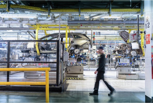
Toyota - Plant area productivity improvement project
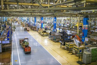
Representation of the Toyota Plant area
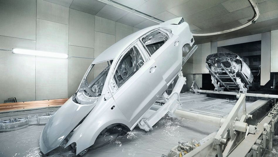
Representation of the Electroplating process for a car
Background:
Toyota Kirloskar Motors is the only Toyota manufacturing plant in India. It consists of two plants, namely plant 1 and plant 2.
I was assigned to the “Spare Parts Loading and Unloading Area” of plant 2 where all the spare parts are loaded onto giant identical dollies called “Skids” for the electroplating process and unloaded after completion of the process.
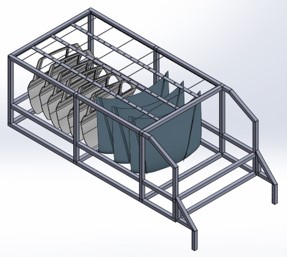
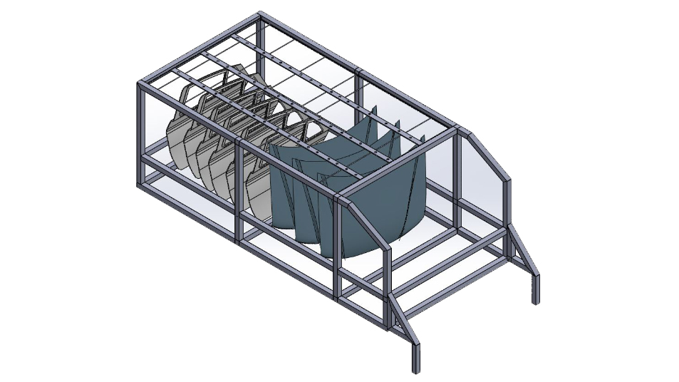
'The Skid' that carries the spare parts
Problem given
I was assigned the task of improving the productivity of the area.
Initial approach:
I studied the area over the next couple of days and spent time with the workers and realized that they were lifting a lot of weight over a sustained period throughout the day, which introduced fatigue naturally and slowed down the process while being detrimental to their health.
I set out to change the way they loaded and unloaded the parts, eliminating fatigue and increasing productivity.
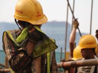
A representative picture showing worker fatigue
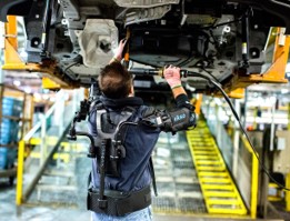
An exoskeleton being used to reduce worker fatigue
Tasks done : To accomplish the project, I performed the following
I surveyed the entire Toyota plant for inspiration
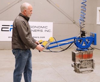
Inspiration was taken from an "Overhead Pneumatic Lifter" that was already being used at another area of the plant
Tasks done:

Old Skid Design
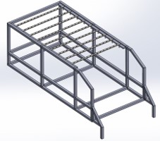
New Skid Design
New Skid Design
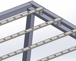
These are detachable members
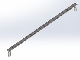
New Structural Roof Cross Member; Material: Plain Carbon Steel
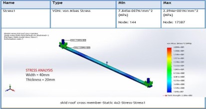
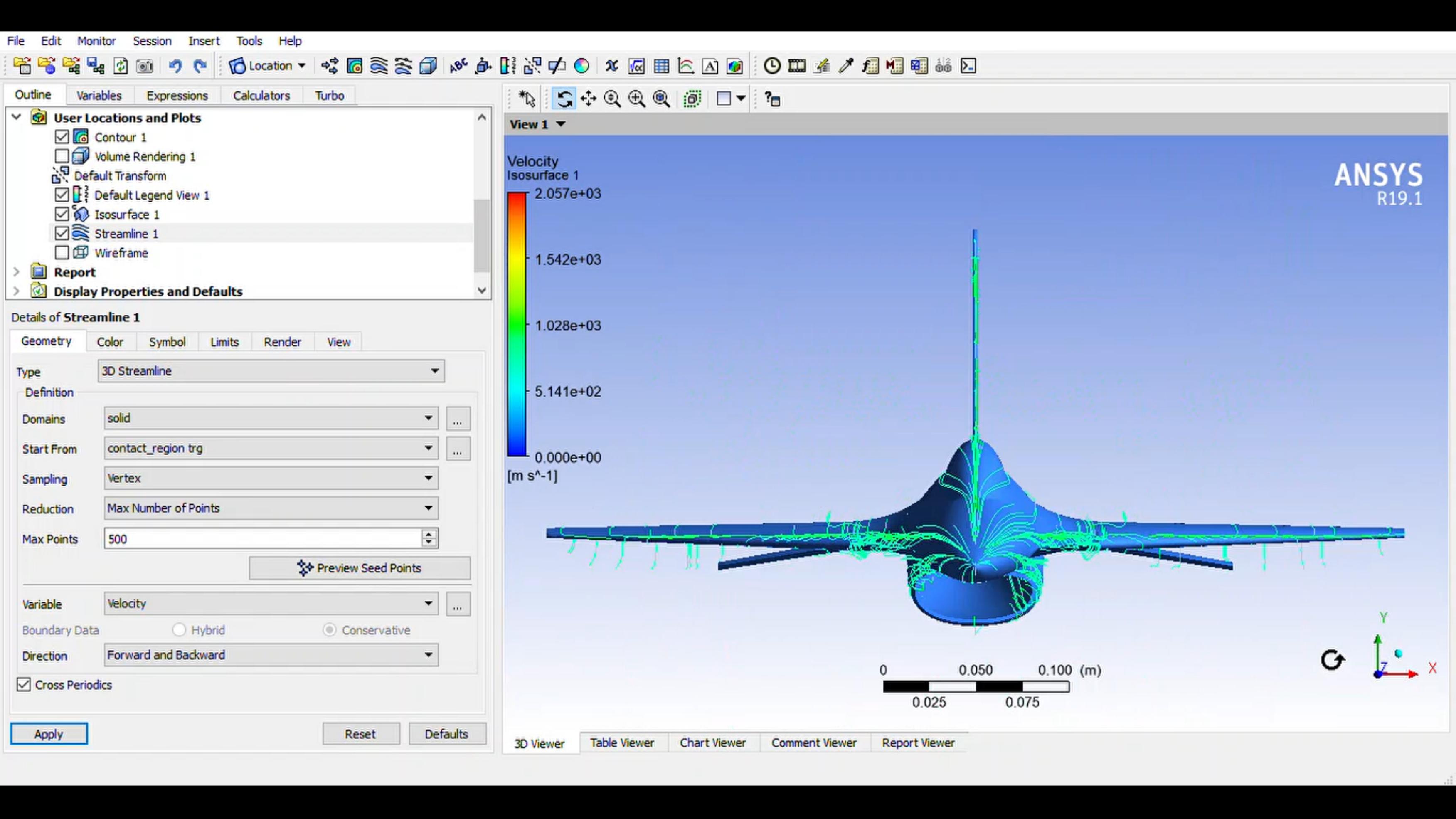
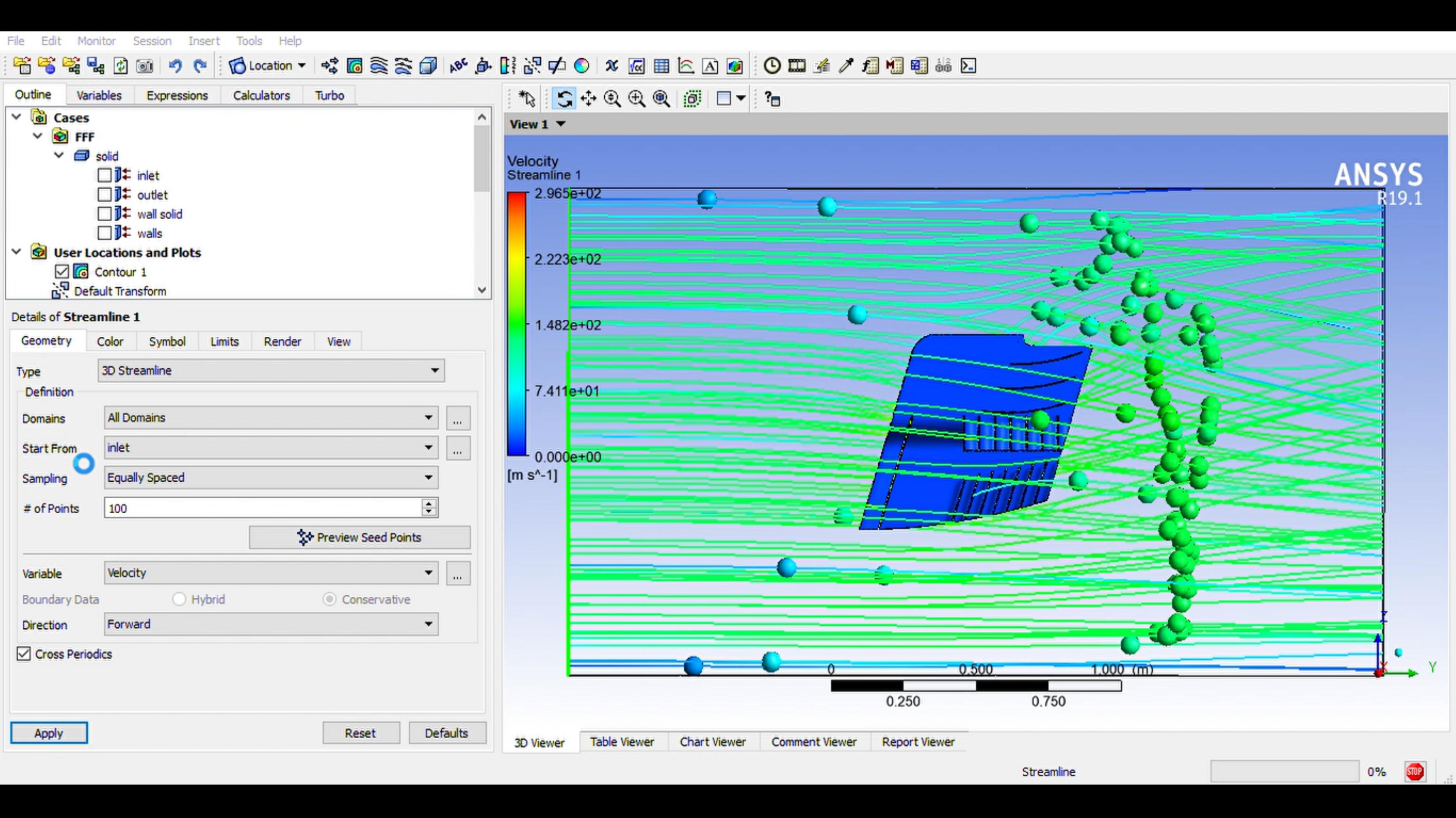
FEA Stress Analysis to validate Structural Integrity and Reliability
Tasks done:
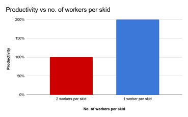
Result:
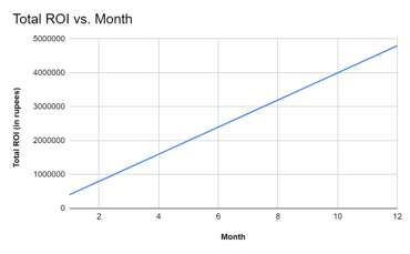
The design was approved for beta testing and was projected to -
BAJA SAE 2k18 Chassis design
Coming Soon
Automobile wheel mounting and dismounting mechanism slideshow
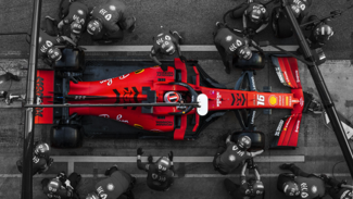
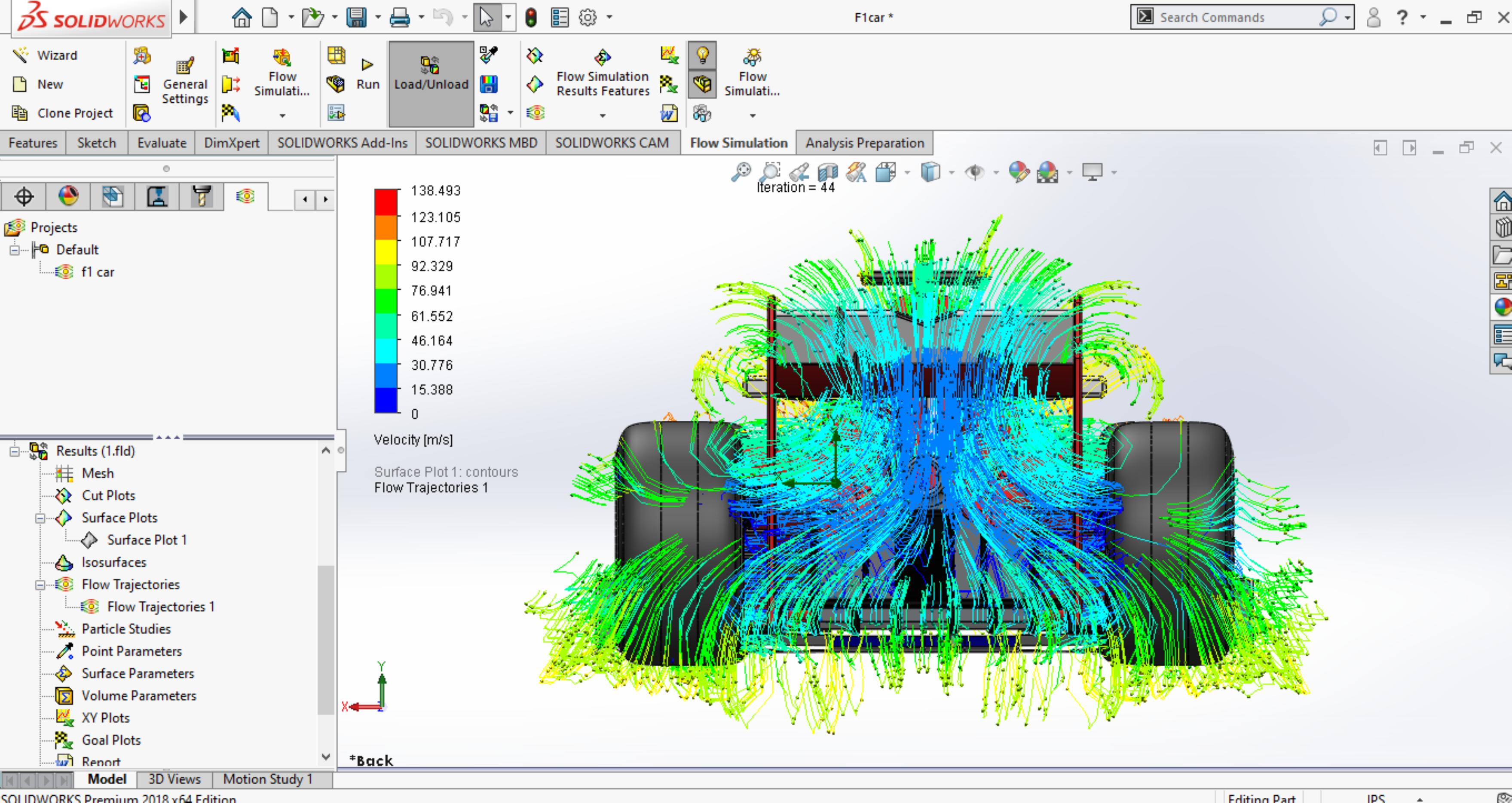
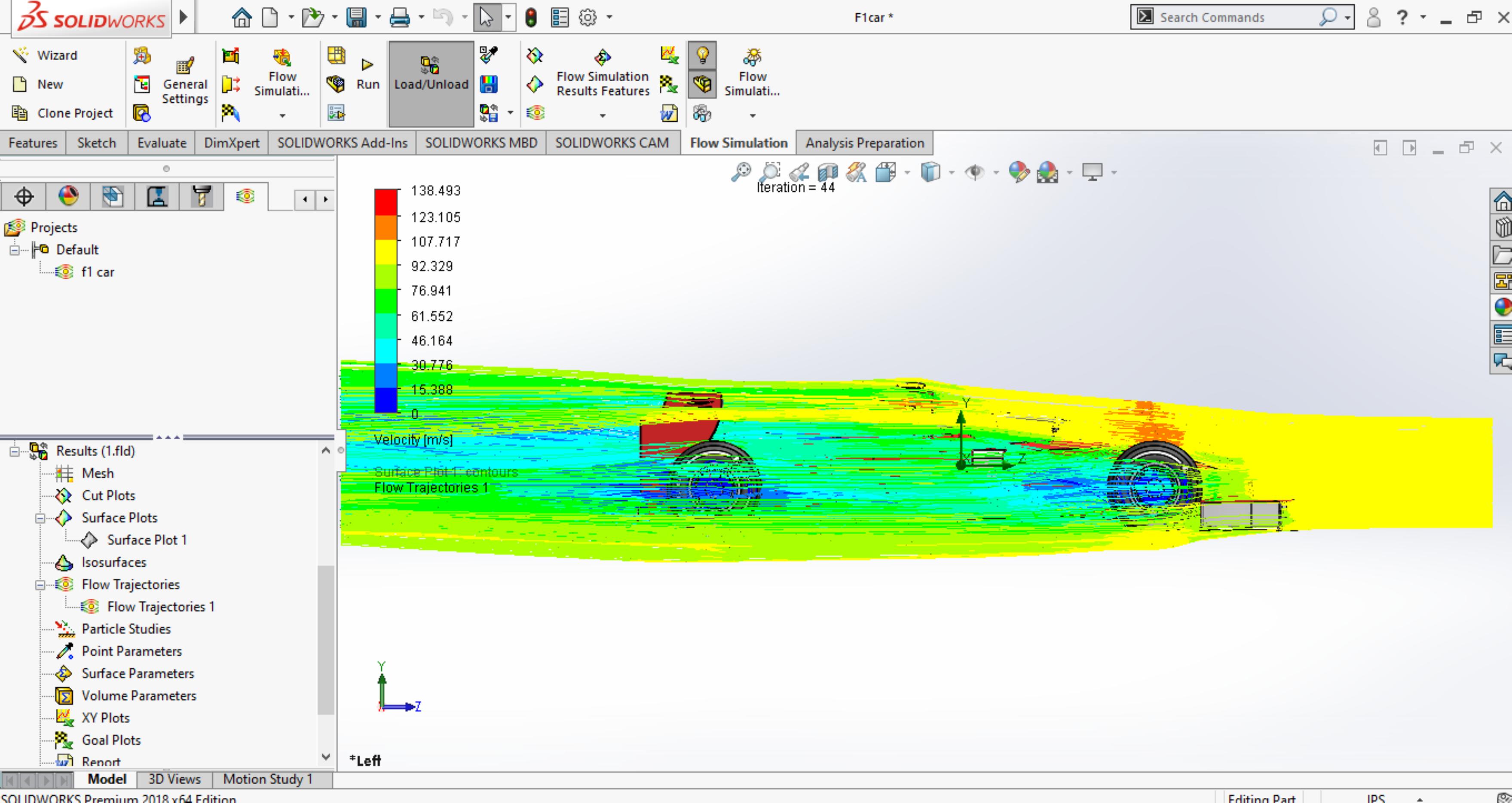
F1 Cars use a single wheel nut for locking and unlocking the wheel
Background:
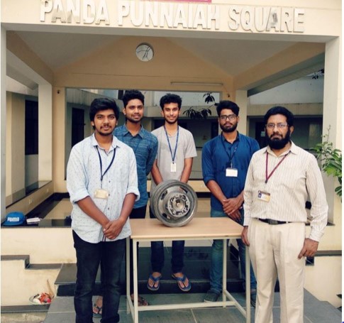
For my senior year project in undergrad, I and three of my classmates chose to design, model, and manufacture a new patent-pending “automobile wheel locking and unlocking mechanism” by our
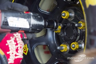
Nascar Cars use lug nuts for locking and unlocking their wheels
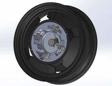
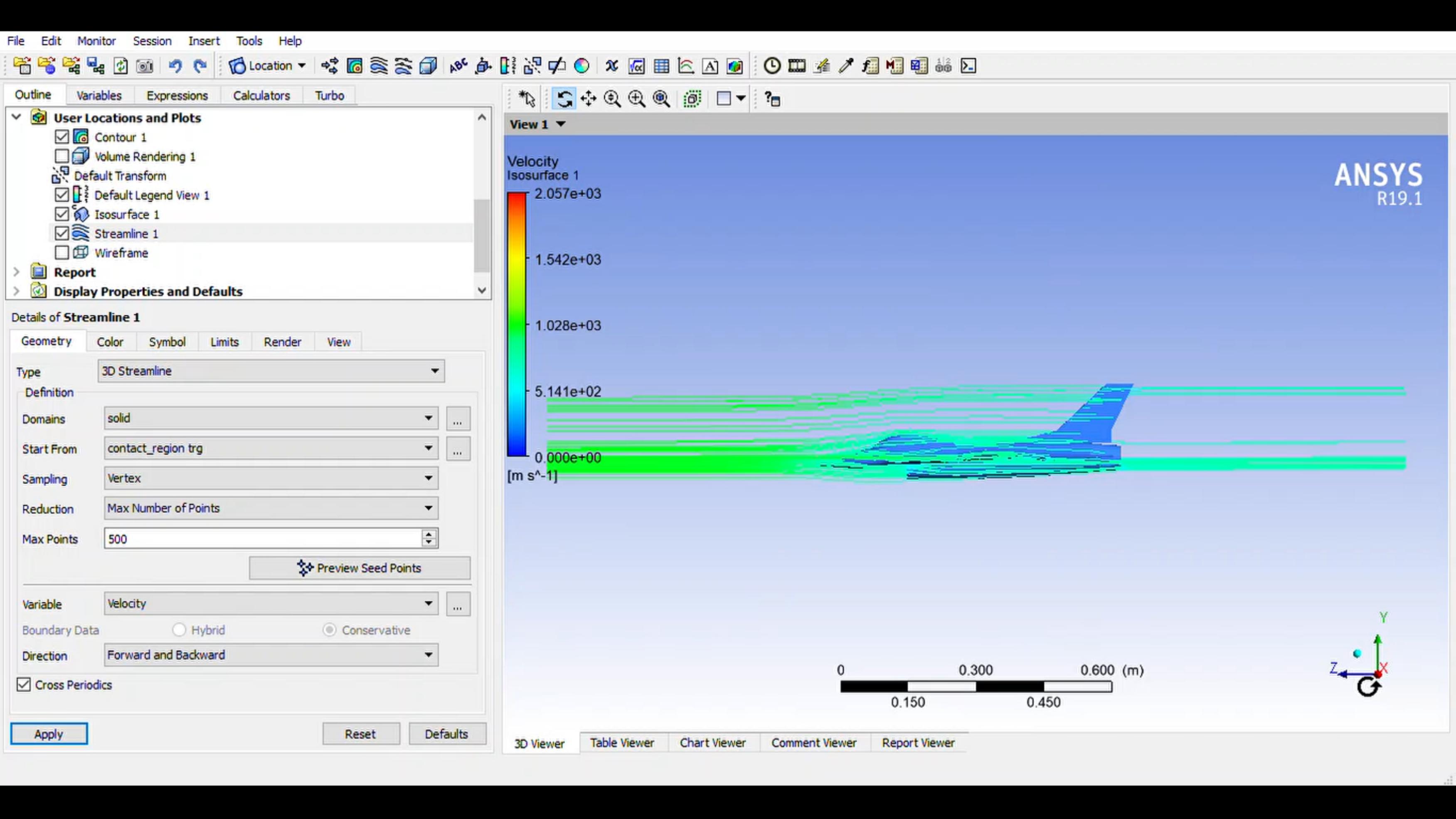
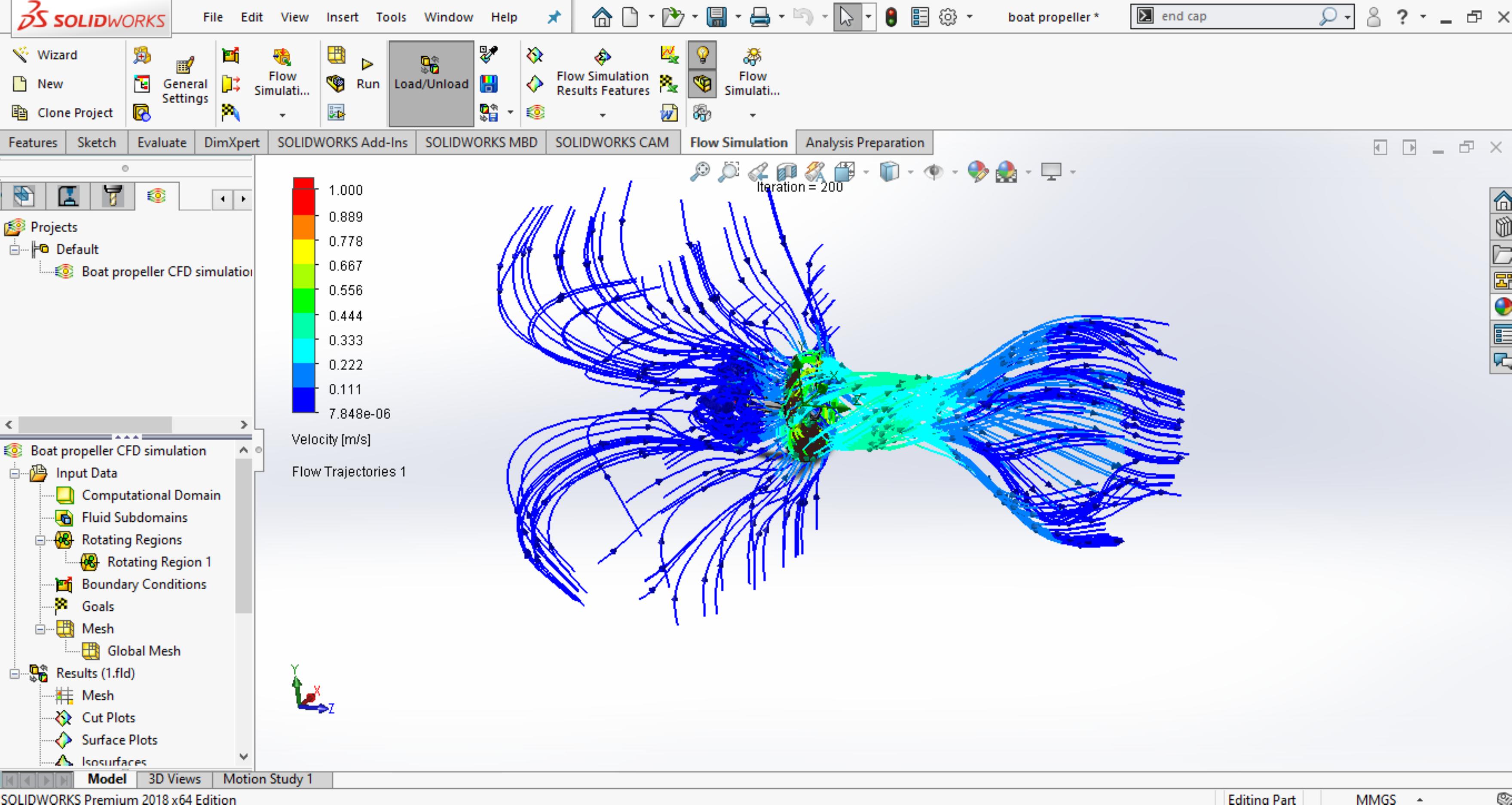
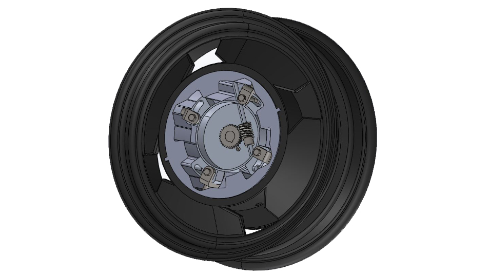
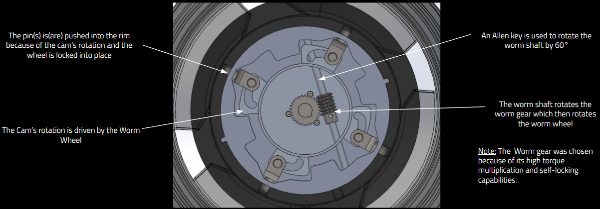
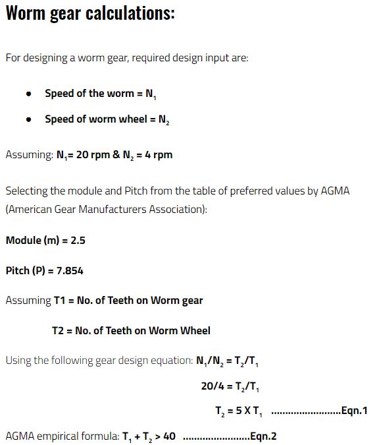
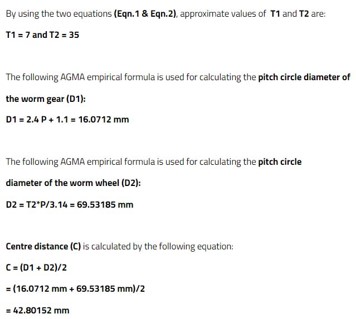
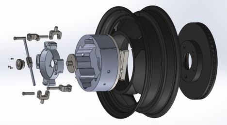
Our Automobile wheel locking and unlocking mechanism uses a worm gear setup
Problem given:
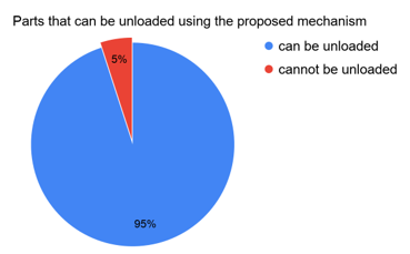
The concept had to be 3D modeled, designed for manufacturing, manufactured, and assembled such that the automobile wheel locks and unlocks radially with a 60° rotation of the Allen key.
Tasks done: accomplish the project, I contributed as follows:
Tasks done:
Exploded view of the 3D model
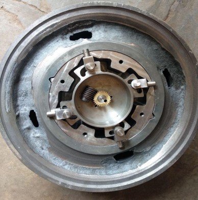
Manufactured Model
Result:
We successfully prototyped the concept and placed among the top 3 teams at the university science fair along with an A grade for our project.
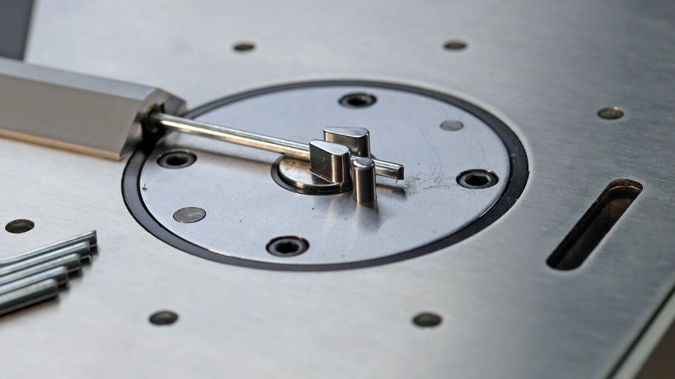
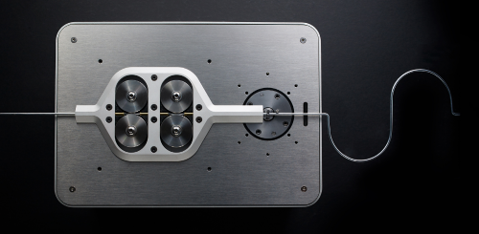
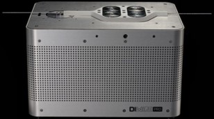
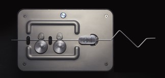
Pensa Labs Air Bending Project
Background:
Pensa Labs manufactures Desktop 2D CNC Wire Bending machines called the “DIWire PRO” and the “DIWire Plus”
Problem given:
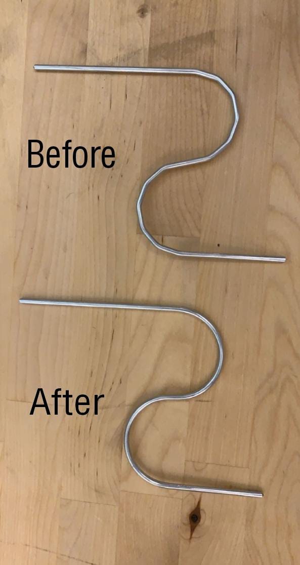
The resolution of the “DIWire PRO” was low, meaning when a circle or another shape with a smooth curvature is introduced, the machine was incapable of bending a smooth curve, instead a polygonal curve was obtained

Part the machine produces

Ideal part
Root Cause:
We looked at all the factors affecting it and it was inhibited by the accuracy of the empirical hardware data available and the equations needed by the software to utilize this data at the time. Thus, me and my fellow software colleague were teamed up to resolve the issue.
Initial approach:
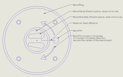
To increase the resolution, we had to reduce the Minimum Feed Distance of the wire.
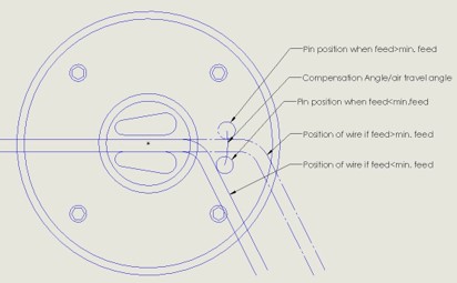
But if we reduced the Minimum Feed Distance, the Bend Pin would hit the bent portion of the wire and not the straight wire.
Thus resulting in the pin traveling in air for a part of its designated bend angle while assuming that the wire is being bent, resulting in an underbent wire.
We set out by trying to compensate for the angle (Compensation Angle) the Bend Pin moves before it touches the wire and starts bending it.
Tasks done: To accomplish the project, I contributed as follows
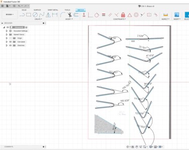
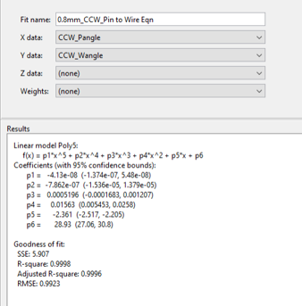
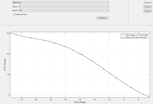
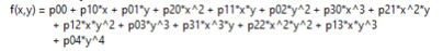
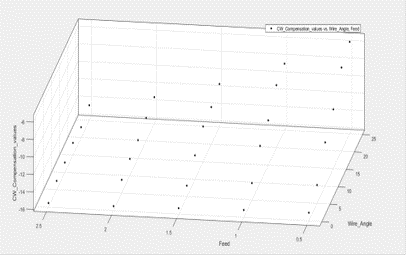
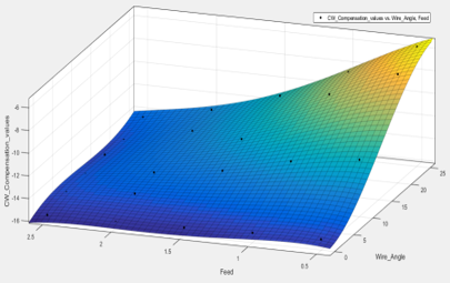
Measuring Wire Angles in CAD for Material Profile creation
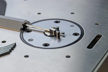
Closeup of the DIWire PRO bending mechanism
Tasks done:
Tasks done:

Result:
The resolution of the machine, its versatility, and its accuracy has increased significantly along with the establishment of a better material profile creation method, a better wire angle measurement method, and other prospects like autonomous material profile creation without measurement because of all the research done in the process.
Swarm Robotics Project

Swarm Robotics Project
Background:
Swarm robotics is a field of multi-robotics in which a large number of robots are coordinated in a distributed and decentralized way.
Swarm Robotics was a Ph.D. level course that I took in my masters and as a part of it, we had to use what we learned in a project to simulate 6 robots in the pybullet python physics environment to undergo multiple formations and transport them from point A to point B while avoiding obstacles along the way.
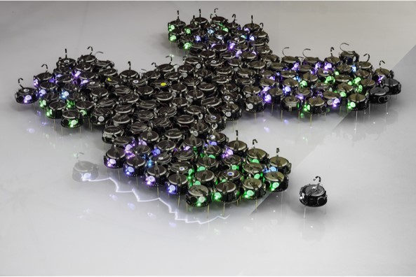
A representation of formation control for multiple robots using decentralized command
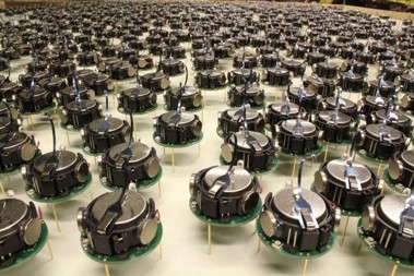
A representation of a 1000 robot formation to show that this can be scaled to any extent
Project Goals:
The 6 Robots start in a rectangle formation in room A, then, they are supposed to perform the following:
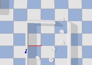
Robots making their way out of room A

Starting formation of the 6 robots

Robots moving out of room A in a vertical linear formation
Result:
I successfully simulated a swarm of 6 robots in the Pybullet physics environment and accomplished all the goals set for the project.
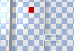
Robots moving into Room B in a horizontal linear formation

Final Equilateral Triangle robot formation
Rectangular formation of the 6 robots
Finite Element Analysis (FEA)